


Application Note for 64Mb HyperRAM Chip ID Read Function
1. PREFACE
Winbond 64Mb HyperRAM is designed with a function called as Chip ID Read (CIDR) function for
customer to identify the unique ID of each chip.
Further to the datasheet, this application note disclose the detail description of CIDR function for
customer easy to use the function for purpose requested by specific application.
2. OPERATION SEQUENCE OF CHIP ID READ FUNCTION
CIDR function is able to be enabled as bleow sequence after power up.
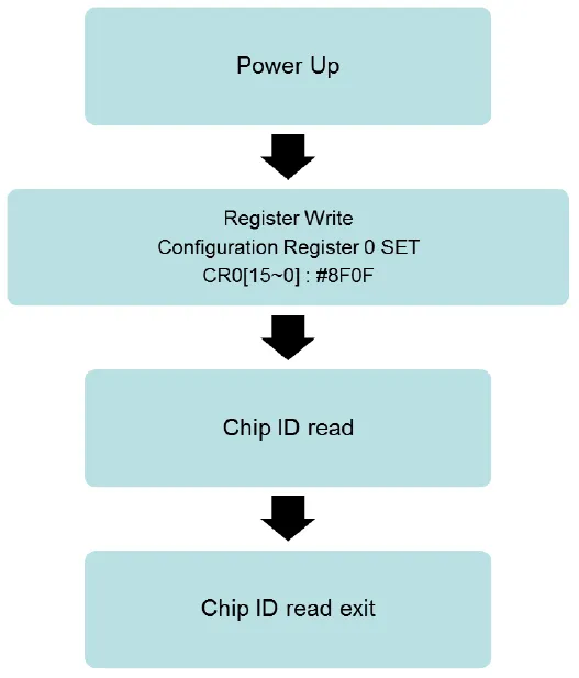
2.1 Register Write:
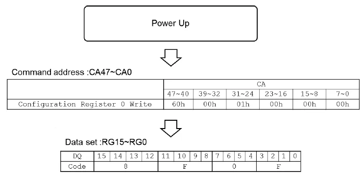
The CIDR write sequence is set “configuration register 0 write” with OP code after power on.
The “configuration register 0 write” is consisted by CA47~CA0, while controlling the state of all address pins as
the OP code, data code is set as 8F0F after CA pin is set, Following is the CIDR enable sequence.
2.2 Chip ID read sequence:
For the Chip ID read sequece, It must be executed by consecutive 3 chip ID code. Each chip ID code will
execute 3 command input with 8 bit test code, Register read is execute after consecutive 3 chip ID code set finish,
and chip ID will be readout at reset rising edge, while tCK must be bigger than 60ns, RESET=High > 30ns,
RESET=Low > 30ns. Following is the Chip ID read sequence.
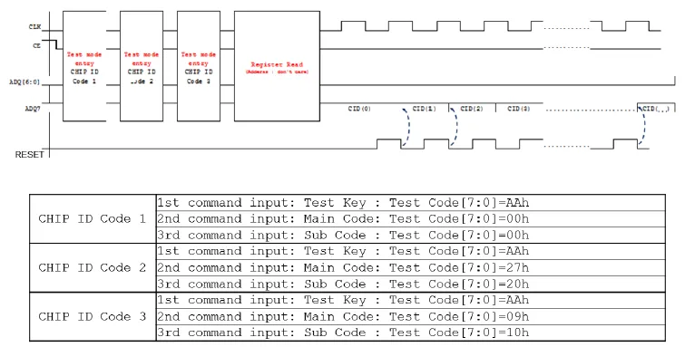
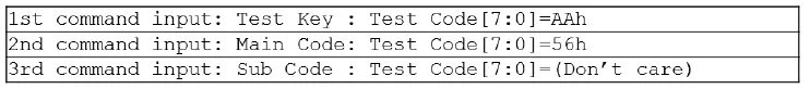
2.2.1 Test mode entry
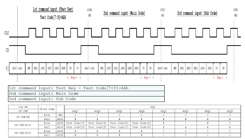
Follow Chip ID read sequece, test mode is entry when each chip ID code is set. Each command input must
write test code into both ADD2 and ADD3. Following is the Chip ID read sequence.
2.2.2 Register Read
Follow Chip ID read sequence, The “configuration register 0 (read)” must be set with OP code before chip ID
readout. The “configuration register 0 (read)” is consisted by CA47~CA0, while controlling the state of all
address pins as the OP code.
The chip ID read must be set 2 Latency count, Initial Latency count =5 clock ; Latency count1 + Latency
count2 =10 clock.

2.2.3 Test mode exit
Test mode is exit after chip ID be readout, Following is the test mode exit code.
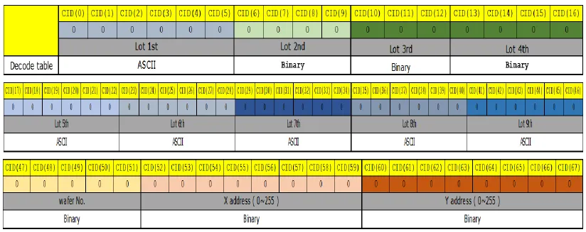
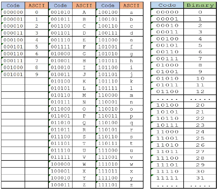
2.3 Chip ID decode
Following is the decode rule when chip ID be readout.
The valid chip ID code is CID[0] to CID[67], when chip ID code be readout after CID[68], they are don’t care.
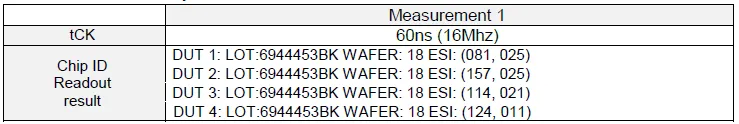
3. MEASUREMENT OF CHIP ID READ SEQUENCE BY MOSAID TESTER
The CHIP ID is correctly readout under below conditions.
4. REVISION HISTORY

The above information is the exclusive intellectual property of Winbond Electronics and shall not be disclosed, distributed or reproduced without permission from Winbond.
